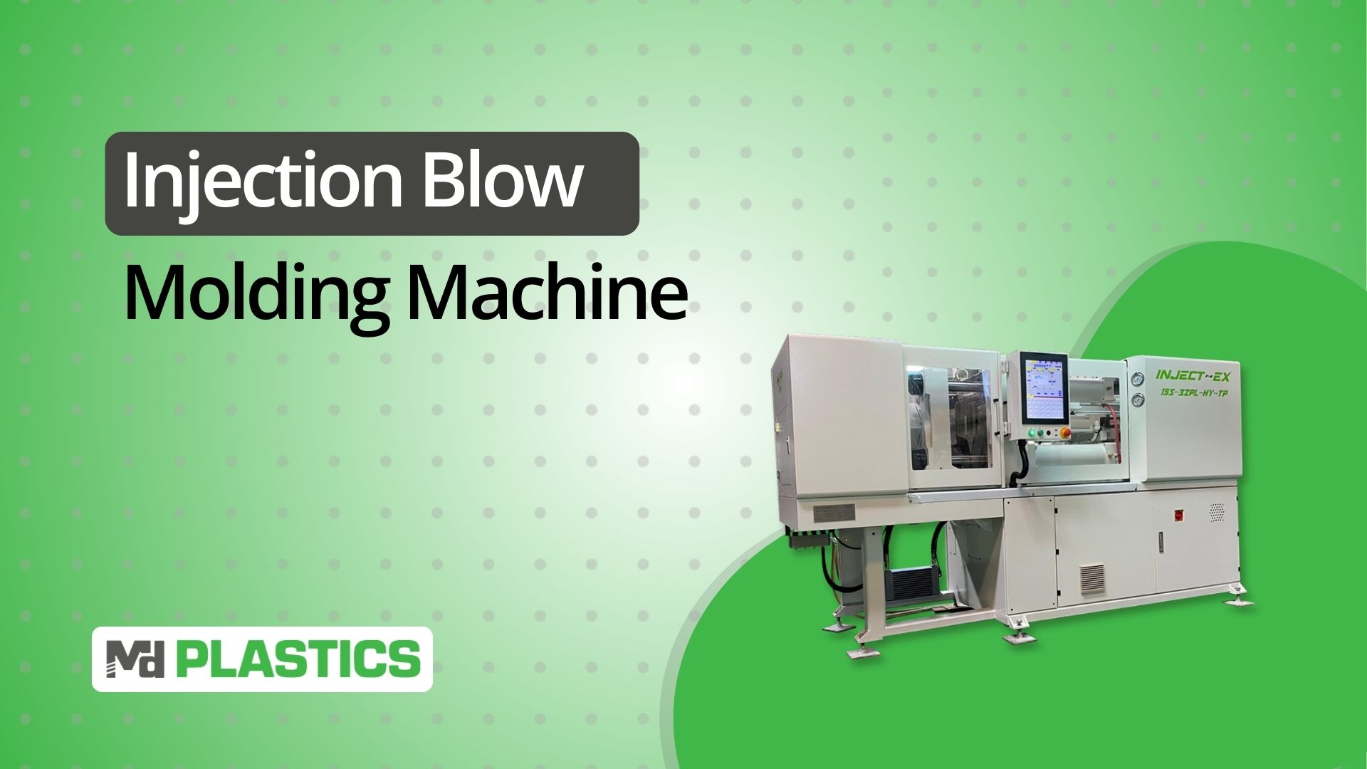
Injection Blow Molding (IBM) is one of the cleanest, most precise ways to produce small-to-medium plastic containers, especially when neck accuracy, clarity, and repeatability matter.
But getting predictable performance from an IBM line comes down to one thing: understanding the machine’s components and how each one influences preform quality, blow behavior, and final part performance.
Most online explanations conflate IBM with extrusion blow molding or omit the machine's anatomy entirely.
That’s a problem, because IBM lives or dies by the condition and alignment of a few critical parts: the injection unit, core rods, neck rings, rotary table, blow molds, and the systems that control temperature, pressure, cooling, and air delivery.
This guide fixes that.
You’ll get a complete, engineer-level breakdown of every major component in an injection blow molding machine, how the 3-station process actually works, where tolerance is won or lost, what wear looks like in the field, and how to select a machine that fits your resin, volume, and container geometry.
If you want accurate, practical information about IBM machine parts, this is the guide you’ve been looking for.
Key Takeaways
IBM is a 3-station process, injection, blow, and cooling, and part quality depends heavily on core rod temperature, alignment, and melt preparation.
The most critical machine parts are the injection unit, core rods, neck rings, preform mold, rotary table, and blow mold. Wear on any of these shows up immediately as ovality, thread defects, haze, or wall-thickness variation.
IBM and extrusion blow molding utilize completely different hardware and materials; IBM is chosen for precision necks and clarity, rather than large hollow parts.
HDPE, PP, PETG, and select PC grades run in IBM. Standard PET requires Injection Stretch Blow Molding (ISBM), not IBM.
Melt stability inside the injection unit controls preform consistency — MD Plastics’ screws, valves, and melt-monitoring tools help processors improve clarity, wall uniformity, and shot repeatability.
Injection Blow Molding in One Look
Injection blow molding runs in a continuous three-station loop. Each station shapes part of the bottle’s final geometry, and each relies on precise temperature and timing to avoid defects.
Station 1: Injection: Forming the Preform on the Core Rod
At the first station, molten polymer is injected into a preform mold directly around a chilled core rod. The core rod defines the internal diameter, while the neck ring forms the threads and sealing surface.
A good preform at this step determines how evenly the material will stretch during blowing.
Indexing Transfer: Rotary Table Movement
Once the preform is set, the rotary turret indexes the entire core-rod/preform assembly to the next station.
Here, alignment and surface temperature are critical; a core rod with incorrect temperature causes uneven blowing, wall-thickness variation, haze, or ovality — not stretch-direction variation.
Station 2: Blow Molding: Expanding to Final Shape
The blow mold closes around the preform, and compressed air enters through the core rod.
The hot preform expands uniformly against the mold walls (no axial stretch as seen in ISBM), forming the bottle or container geometry with controlled wall distribution and clarity.
Station 3: Cooling & Ejection: Locking in Final Dimensions
With the part fully expanded, the system manages cooling through the blow mold and the core rod. Proper cooling prevents ovality, sink, and finish distortion.
Once stable, the mold opens, and automation removes the part before the core rod returns to the injection station.
IBM’s three-station method produces high-precision neck finishes, excellent clarity, and highly uniform wall thickness, making it the preferred choice for pharmaceutical, cosmetic, and small food-grade containers.
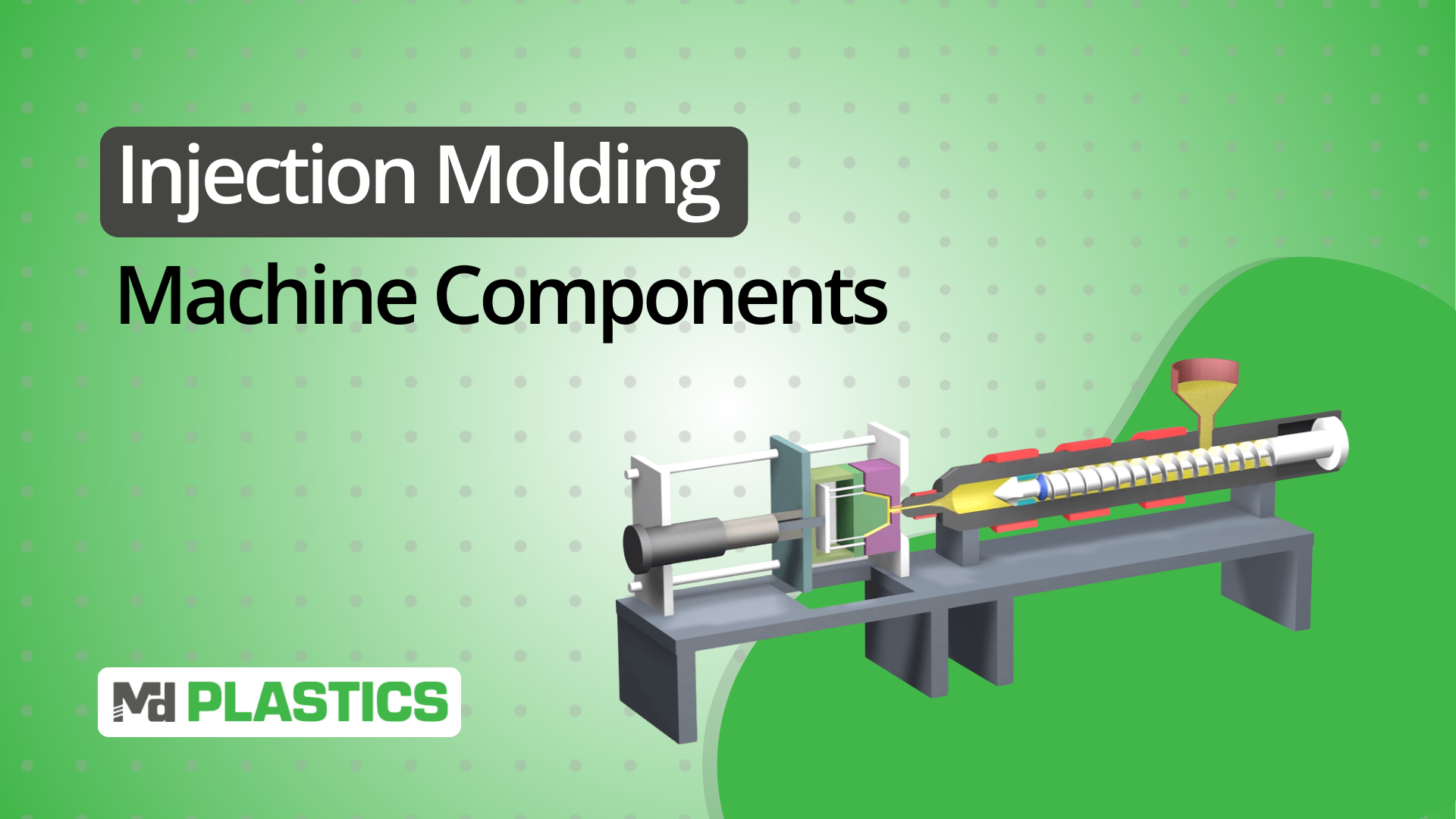
The Anatomy of an Injection Blow Molding Machine
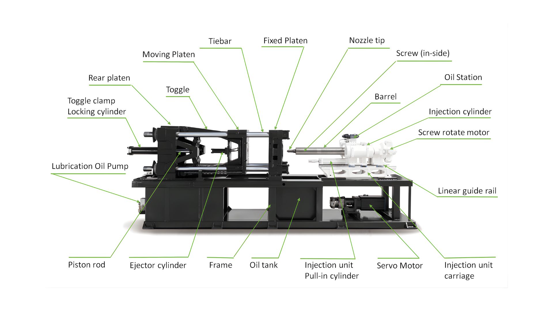
Injection Blow Molding (IBM) is unforgiving. The melt must be prepared perfectly, the preform must be dimensionally correct before transfer, and every station must stay synchronized.
To understand why IBM produces unmatched neck finishes and clarity, you need to understand what each component actually governs inside the cycle.
Below is a functional breakdown of every major IBM machine component, including the engineering dependencies, failure symptoms, and what tolerances matter most.
1. Injection Unit (Where Melt Quality Begins)
The injection unit determines everything about preform consistency. Poor melt prep cannot be corrected downstream.
Core elements:
Barrel: Sets thermal profile that defines melt viscosity.
Screw: Melts, mixes, and meters shot volume. Geometry affects residence time, shear profile, and material clarity.
Non-Return Valve (NRV): Shot integrity; leakage causes preform short shots.
Nozzle: Provides clean melt transfer and thermal stability at the gate.
What it controls:
Melt temperature uniformity
Preform fill balance
Clarity (shear + thermal history)
Neck-finish dimensional consistency
Thread-forming definition at the preform gate
Failure symptoms:
Stringing or splay
Preform short shots
Inconsistent wall thickness
Haze caused by thermal fluctuations
Weight variability
2. Core Rod Assembly (The Most Critical Part in IBM)
The core rod sets the internal shape, supports the preform during transfer, and delivers blowing air.
It is also the single component that touches the part in every station.
Functions:
Defines the inside diameter and stretch ratio
Maintains preform geometry during indexing
Contains cooling channels that freeze the wall structure and clarity
Provides the air pathway for blowing
Why it matters:
Any deviation in surface finish, straightness, or temperature uniformity instantly appears in the bottle as ovality, haze, or inconsistent wall distribution.
Wear symptoms:
Wall thickness shift (one side heavier)
Cloudiness near the base
Sink around the neck-support ring
Sticking during transfer
High-end IBM lines treat the core rod as a precision tool, not a consumable.
3. Neck-Ring / Finish Tooling (Where Sealing Performance Is Made or Lost)
The neck finish, threads, sealing surface, and tamper band are the most controlled features on a bottle. IBM excels here because the neck ring forms the finish before blowing.
Functions:
Shapes threads to cap/closure specs
Holds the preform securely during transfer
Maintains concentricity relative to the core rod
Failure symptoms:
Flash at the neck
Misaligned threads
Poor cap fit/leak failures
“High neck” or “short neck” dimensional drift
A worn neck ring is one of the most common causes of packaging line rejection.
4. Preform Mold (Defines How Well the Bottle Will Blow)
Unlike extrusion blow, IBM begins by forming a precision preform.
Functions:
Controls the preform wall profile → directly determines final bottle wall thickness
Steel grade affects cooling speed and mold life
Venting prevents gas traps and incomplete fill
Cooling circuits stabilize the preform so it survives the transfer
Failure symptoms:
Preform warpage → bottle distortion
Short shots
Poor clarity from hot spots
Thread distortion can stem from neck-ring misalignment, uneven cooling, thermal imbalance, or injection pressure spikes.
IBM’s tight downstream control depends on a stable, dimensionally correct preform.
5. Rotary Indexing Table / Turret (The Synchronization Backbone)
This mechanism rotates the core rod assemblies between Injection → Blow → Ejection.
Engineering requirements:
High positional accuracy
Repeatable indexing timing
Tight thermal control around the core-rod mounts
Smooth acceleration to avoid deflection of hot preforms
Failure symptoms:
Misaligned blow mold closure
Seam shift on finished bottles
Stretched or deformed preforms during transfer
A sloppy indexing system ruins process repeatability.
6. Blow Mold (Final Part Geometry + Cooling Authority)
The blow mold is where clarity, contour accuracy, and surface finish are set.
Functions:
Governs wall distribution during expansion
Pulls heat out fast → determines cycle rate
Defines surface texture, ribs, and logos
Controls base formation and push-up stability
Failure symptoms:
Oval bottles (uneven cooling)
Stiff base / soft base variation
Surface haze
Parting-line mismatch
With IBM, the blow mold is less about forming and more about managing heat extraction.
7. Blow Air System / Blow Pin Pathway (Stretch + Expansion Behavior)
Blow air enters through the core rod, making the pathway design critical.
Controls:
Stretch behavior of the hot preform
Final wall thickness distribution
Crystal clarity (air timing + pressure curves)
Base formation
Failure symptoms:
Uneven expansion
Weak shoulders
Cloudy panels
Air entrapment marks
The airflow profile is as important as the mold temperature.
8. Clamping System (Dual-Function: Injection & Blow)
IBM uses two distinct clamps:
Injection Clamp
Holds the preform mold closed during filling
Must handle injection pressures without deflection
Blow Clamp
Holds the blow mold closed during high-pressure expansion
Alignment affects seam visibility and ovality
Failure symptoms:
Flash on neck or body
Parting-line mismatch
Seam thickening
9. Cooling System (The Cycle-Time Limiter)
Cooling is more complex than in injection molding because:
Preform cools on a metal core rod
The bottle cools inside the blow mold
Heat extraction must be consistent across three stations
Turret cooling is also critical to ensure consistent core-rod temperatures across stations.
Cooling paths include:
Core rod cooling
Neck ring cooling
Blow mold cooling
Injection mold cooling
Failure symptoms:
Ovality
Inconsistent transparency
Cycle-time drift
Blow mold sticking
10. Hydraulic / Pneumatic Systems (Motion Accuracy = Part Accuracy)
These systems' power:
Mold open/close
Turret rotation
Core rod movement
Neck ring slides
Ejectors
Take-out
Failure symptoms:
Slow cycle
Index lag
Incomplete clamp
Flash or deformation
Random downtime
Pneumatic stability especially affects blow timing and bottle clarity.
11. Control System (PLC / HMI: Where Repeatability Lives)
A modern IBM PLC governs:
Barrel temperature zones
Injection pressures & speeds
Transfer timing
Blow pressure profile
Mold cooling sequencing
Alarms and diagnostics
A weak control system equals:
Weight drift
Inconsistent neck dimensions
Unpredictable startup/shutdown behavior
Process repeatability = machine control discipline.
12. Take-Out / Automation (Where Damage Often Happens)
A good IBM take-out system removes hot bottles without distortion.
Functions:
Eliminates operator variability
Ensures uniform cooling after release
Supports high cavitation without part damage
Failure symptoms:
Oval finish
Scuff marks
Soft-base deformation
Random reject spikes
With the core IBM components identified, it helps to contrast them with extrusion blow systems. Many processors use the terms interchangeably, but the equipment, tooling, and part capabilities are fundamentally different.
Injection Blow vs Extrusion Blow Molding
Injection blow molding (IBM) and extrusion blow molding (EBM) both create hollow plastic parts, but the machine architecture, tooling, material behavior, and achievable tolerances are fundamentally different.
This comparison breaks down the differences in a way that engineers can evaluate at a glance.
Preform vs Parison Formation
IBM:
A fully formed preform is injection molded around a precision core rod.
The neck finish is created in the injection station and remains dimensionally fixed.
Melt quality and shot consistency directly affect clarity and wall uniformity.
EBM:
A molten parison is extruded vertically from a die head.
Wall thickness depends on die gap control, melt strength, and parison programming.
Neck geometry is formed during pinch-off, not injection—lower accuracy.
Key Difference: IBM uses a solid, molded preform; EBM uses a molten, hanging parison.
Core Rod vs Die-Head Extruder
IBM:
Core rods set internal diameter, stretch behavior, and final bottle symmetry.
Cooling channels inside the rod stabilize neck and shoulder formation.
Coordinated timing between stations maintains dimensional repeatability.
EBM:
The die head creates the parison and may incorporate parison programming for thickness control.
No core rod, shape forms entirely by inflation and mold geometry.
Highly dependent on melt strength and extrusion stability.
Key Difference: IBM’s core rod creates consistency; EBM relies on melt strength and timing.
Tooling: Injection + Blow Molds vs Single Blow Mold
IBM:
Requires two tool sets:
Injection preform mold
Blow mold (final shape)
Higher tooling precision allows better cosmetic detail and dimensional accuracy.
EBM:
Uses a single blow mold with a pinch-off region.
Tooling is simpler, but less detailed flash removal is usually required.
Key Difference: IBM tooling is more complex but delivers substantially better finish quality.
Material Compatibility
IBM:
Best with materials requiring high clarity and precision:
PP
PETG
PC
HDPE (for some applications)
EBM:
Best with resins with high melt strength:
HDPE (dominant)
PP
PVC
Multilayer barrier structures (EVOH)
Key Difference: IBM = clarity + precision; EBM = strength + wall distribution.
Neck Finish Accuracy & Part Quality
IBM:
Neck threads and sealing surfaces formed during injection—high accuracy.
Excellent dimensional repeatability.
Ideal for products requiring leak-proof or torque-controlled closures.
EBM:
Finish formed during mold pinch-off—lower accuracy.
Slight ovality or flash can occur depending on the mold condition.
Key Difference: IBM dominates where closure performance matters (pharma, personal care).
Typical Applications
IBM:
Small to medium bottles
Pharmaceutical & nutraceutical containers
Eye-dropper and spray bottles
Personal care packaging
High-clarity cosmetic containers
EBM:
Large bottles (detergent, milk, oils)
Automotive ducts
Jerry cans
Industrial drums
Larger hollow goods
Energy Use, Tooling Cost & Production Efficiency
IBM:
Higher tooling cost due to dual mold sets and precision cores.
Lower material waste (no flash).
Superior repeatability → lower reject rates.
EBM:
Lower tooling cost.
Higher scrap due to flash and trimming.
More forgiving of large part sizes.
At-a-Glance Comparison Table
Feature / Requirement | Injection Blow Molding (IBM) | Extrusion Blow Molding (EBM) |
|---|---|---|
Formation | Injection-molded preform on core rod | Extruded parison from die head |
Neck Finish | Molded in injection—highest accuracy | Pinch-off formed—moderate accuracy |
Core Element | Core rod controls ID, stretch, and cooling | No core rod; relies on parison control |
Tooling | Injection + blow mold (dual) | Single blow mold (+ trim) |
Wall Uniformity | Very consistent (preform-based) | Variable (depends on parison programming) |
Clarity / Cosmetics | High (PETG/PP/PC) | Moderate |
Materials | PP, PETG, PC, clarified HDPE (select grades) | HDPE, PP, PVC, multilayer EVOH |
Part Size | Small–medium | Small–very large |
Scrap | Low (no flash) | Higher (flash/trim) |
Tooling Cost | Higher (precision cores) | Lower |
Use IBM when neck accuracy, clarity, and repeatability are non-negotiable (pharma, personal care). Use EBM for larger volumes/sizes and when wall programming and cost take priority (detergent, jerry cans).
With the differences between IBM and EBM clear, the next question is one engineers ask early in any project: Which materials actually run well in blow-based processes and why?
That’s where resin behavior, melt strength, and clarity requirements start to narrow the options.
Let’s break down the blow-extrusion materials that consistently deliver reliable processing and part performance.
Blow Extrusion Materials: What Runs Well and Why
Blow molding, whether extrusion blow or injection blow, depends heavily on melt strength, viscosity behavior, and cooling response. Not every resin can form a stable parison or withstand stretch without thinning unevenly.
Below is a concise, engineer-level breakdown of the resins that consistently perform well in blow-based processes and the reasons why.
1. HDPE (High-Density Polyethylene)
Why it runs well:
Naturally high melt strength → holds shape during parison formation
Excellent ESCR (environmental stress crack resistance)
Predictable cooling and shrinkage behavior
Used for: Detergent bottles, milk jugs, automotive ducts, and industrial containers.
EBM vs IBM:
EBM: Extrusion blow molding (EBM). HDPE is the workhorse resin for EBM due to its stability during free-hanging parison formation.
IBM: Limited, HDPE can run in IBM, but clarity is poor, and wall control is less precise.
2. PP (Polypropylene)
Why it runs well:
High stiffness and heat resistance
Good hinge strength
Lower density = lightweight parts
Used for: Thin-walled packaging, clarified personal-care bottles, and technical parts requiring rigidity.
EBM vs IBM:
EBM: Works well but requires more parison control due to lower melt strength than HDPE.
IBM: Runs well for small bottles with precise neck finishes and better clarity than HDPE.
3. PETG (Glycol-Modified PET)
Why it runs well:
Excellent clarity
Good impact resistance
Low haze and high gloss
Used for: Cosmetic packaging, medical tubes/containers, and premium small bottles.
EBM vs IBM:
IBM: Preferred, PETG provides high clarity without stretch-blow equipment.
EBM: Less common due to lower melt strength.
4. PVC (Polyvinyl Chloride)
Why it runs well:
Good strength and clarity
High melt elasticity in many grades
Stable wall distribution during inflation
Used for: Specialty bottles, chemical containers, and technical parts.
EBM vs IBM:
EBM: Common for technical-grade containers.
IBM: Possible but less common due to heat sensitivity during preform molding.
5. PC (Polycarbonate)
Why it runs well:
Extremely high impact strength
Good clarity
Dimensional stability after blowing
Used for: Medical containers, technical housings, safety-related components.
EBM vs IBM:
IBM: Preferred, PC benefits from preform-based precision and better thermal control.
EBM: Possible but requires very tight temperature management.
6. Multilayer / Barrier Resins (EVOH, Tie-Layers)
Why they run well:
Provide gas barrier performance for food, fuel, and chemical packaging
Enable long shelf life and odor control
Used for: Fuel tanks, food-grade bottles, specialty pharma packaging.
EBM vs IBM:
EBM: Dominant, multilayer structures are typically co-extruded during parison formation.
IBM: Rare, IBM isn’t typically used for barrier multilayer structures due to tooling and preform complexity.
Where Each Resin Fits: IBM vs EBM
Resin | Best for EBM | Best for IBM | Why |
|---|---|---|---|
HDPE | ✔✔✔ | ✔ (limited) | High melt strength ideal for parisons |
PP | ✔✔ | ✔✔ | Good stiffness; workable in both |
PETG | ✔ (limited) | ✔✔✔ | High clarity, great for preform-based forming |
PVC | ✔✔ | ✔ | Heat-sensitive but blow-friendly |
PC | ✔ (technical only) | ✔✔✔ | Demands tight thermal control |
EVOH ML | ✔✔✔ | ✖ | Co-extrusion is favored for multilayer barriers |
Choosing the right resin matters as much as choosing the right machine—material behavior defines parison stability, stretch response, wall uniformity, and clarity long before the mold ever closes.
Note: Injection stretch blow molding (ISBM) is a separate process used for PET bottles and should not be confused with IBM.
Tolerances, Finish & Typical Applications for Injection Blow Molding
Injection blow molding exists for one primary reason: precision. When small and medium-sized containers need accurate neck finishes, repeatable wall thickness, and near-injection-molding-level clarity, IBM consistently outperforms other blow molding methods.
Why IBM Excels at Tight Tolerances
Unlike extrusion blow molding, IBM begins with a fully injection-molded preform created on a core rod with controlled dimensions, cooling, and material distribution. This gives IBM several built-in accuracy advantages:
Neck finish is molded, not formed, so threads, sealing surfaces, and shoulder geometry stay within tight tolerances.
Wall thickness starts uniformly due to the preform’s injection-defined geometry.
Minimal flash and parting-line defects, because there’s no parison pinch-off step.
Core rod stability ensures the preform stays centered during blowing, reducing ovality.
The result: dimensional repeatability that’s significantly better than extrusion blow.
Superior Cosmetic and Optical Finish
IBM parts typically achieve higher clarity and gloss because:
The injection-molded preform has a smooth, fully packed surface.
Stretch during blowing is controlled by the core rod’s thermal profile.
No parison sag or deformation can introduce haze.
For PETG, PP, PC, and certain clarified resins, IBM consistently produces clearer, more uniform containers than EBM.
Where IBM Is the Best-Fit Process
IBM shines in markets where precision + aesthetics + functional sealing matter:
Pharmaceutical & Healthcare
Dropper bottles
Nasal spray vials
Diagnostic sample containers
Sterile packaging
Tight neck tolerances ensure secure closures, dosage accuracy, and regulatory compliance.
Personal Care & Cosmetics
Travel-size bottles
Lotion containers
High-clarity PETG bottles
These products rely heavily on surface quality and consistent wall thickness.
Food & Beverage
Flavoring bottles
Concentrates
Single-serve items
IBM delivers consistent neck threads to guarantee leak-free sealing.
Technical / Specialty Packaging
Laboratory containers
Chemical dispensing bottles
High-precision dosing bottles
Uniform walls support predictable drop strength and performance.
Why Cap & Closure Compatibility Is a Major IBM Advantage
Closures are often the most unforgiving part of a package. A slight issue with the finish can cause:
Leaks
Over-torquing
Cross-threading
Poor tamper-evidence performance
IBM’s ability to mold the finish directly from the injection cavity ensures:
Accurate thread pitch
Consistent sealing of land
Stable neck ID/OD
Minimal ovality
This is a major reason IBM dominates pharmaceutical and cosmetic packaging.
IBM is chosen not because it’s the cheapest or fastest method, but because it delivers the precision, clarity, and dimensional stability required for small–medium bottles with strict functional and cosmetic requirements.
Common Wear Parts & Failure Symptoms
Your Maintenance Cheat Sheet!
Even the best injection blow molding machines drift out of spec over time, not because of bad operation, but because the parts that define accuracy slowly wear.
This section gives you a fast, engineering-first diagnostic map: what wears, why it wears, the defects it causes, and what to check during maintenance.
1. Core Rod Wear (Highest-Impact Wear Component)
The core rod determines preform wall uniformity, clarity, and final bottle geometry. As the rod wears, even slightly, the effects show up immediately in part quality.
Wear Causes
Repeated thermal cycling
Micro-abrasion from resin (especially glass-filled)
Poor cooling-water quality is causing internal scaling
Contact wear at transition points
Failure Symptoms
Wall thickness is drifting toward one side
Loss of clarity or internal flow marks
Ovality after blowing
Stretch behavior inconsistency
What to Inspect
Rod diameter at multiple points
Surface polish (Ra) stability
Cooling-channel flow rate
Alignment with the neck ring and blow mold
Maintenance Interval: Inspect every 1–3 months, depending on resin and volume.
2. Neck-Ring / Finish Tooling Wear
The neck ring forms the finish, which is the most functionally critical feature of IBM packaging. Small wear = big problems.
Wear Causes
Mechanical impact during opening/closing
Overheating
Resin leakage at the finish area
Repeated contact with the core rod
Failure Symptoms
Thread flash
Cross-threading or mis-threading
Dimensional drift → leaking closures
Finish ovality
What to Inspect
Thread profile
Sealing-land flatness
Parting-line condition
Fit against cothe re rod
Maintenance Interval: Inspect every 2–6 weeks on high-volume pharmaceutical/consumer lines.
3. Blow Mold Wear or Cooling Channel Blockage
Blow molds rarely fail structurally, but cooling deterioration causes more defects than tooling wear itself.
Wear/Blockage Causes
Mineral scale in cooling lines
Corrosion (especially in hard water environments)
Impact wear at parting-line surfaces
Cavitation erosion from aggressive cooling
Failure Symptoms
Ovality
Inconsistent wall distribution
Random clarity streaks from uneven cooling
Slow cycle time from poor heat extraction
What to Inspect
Cooling-channel flow and temperature differential
Parting-line wear
Mold-base flatness
Localized hotspots using IR measurement
Maintenance Interval: Descale quarterly; inspect mold surfaces every 4–8 weeks.
4. Injection Nozzle or Non-Return Valve (NRV) Wear
The injection side defines the preform quality, which defines everything that happens downstream. A worn nozzle or NRV disrupts melt delivery long before other defects appear.
Wear Causes
Abrasive resin grades (GF, mineral-filled)
High backpressure settings
Excessive decompression
Poor melt filtration upstream
Failure Symptoms
Short shots
Stringing/drooling at injection
Inconsistent shot size
Color streaking from poor mixing
What to Inspect
Valve sealing land
Nozzle tip surface condition
Valve spring response (for check valves)
Melt pressure stability
Maintenance Interval: Inspect every 1–2 months; replace valves annually on high-volume lines.
5. Hydraulic & Pneumatic System Drift
IBM relies heavily on controlled motion between stations. Hydraulic or pneumatic issues show up as timing and symmetry defects, not just speed issues.
Wear Causes
Seal failure
Pressure regulator drift
Valve is sticking from contamination
Air/oil temperature instability
Failure Symptoms
Slow or uneven indexing
Incomplete mold closure → seam marks or flash
Blow-pin timing issues
Variability in cycle time
What to Inspect
Cylinder seal condition
Pressure/flow stability
Valve response time
Air quality (dry, filtered)
Maintenance Interval: Weekly pressure checks; full system inspection quarterly.
These wear patterns are predictable, and once you know what each component controls, IBM troubleshooting becomes faster, cleaner, and far more repeatable.
Selecting an Injection Blow Molding Machine
Most IBM machines look similar from the outside: three stations, a turret, a clamp. But the performance spread between models is huge, and it comes down to a handful of specs that directly affect bottle geometry, clarity, and output rate.
Here’s how experienced processors evaluate a machine not by brochure numbers, but by what shapes day-to-day production.
Start With the Mold, Not the Machine
Every IBM decision begins with the part:
Bottle size
Neck finish
Wall-thickness target
Clarity expectations
Annual volume
Once that’s fixed, the machine specs fall into place.
Clamp Capacity: Can It Hold the Mold Itself?
IBM needs two independent clamps.
Processors usually size them based on:
Injection clamp → must resist cavity fill pressure (preforms with thick bases need more).
Blow clamp → must hold long enough for the preform to stretch and settle without tempting flash.
Most plants oversize tonnage “for safety” and end up with slower cycles. The goal isn’t brute force; it’s repeatable closure.
Shot Capacity: The Actual Constraint Nobody Talks About
The bottle’s entire mass is created in the preform stage. IBM requires extremely tight shot-size repeatability because even small weight variations create downstream blowing inconsistencies.
If shot size is mismatched:
Too small → short shots, base collapse, or poor material distribution
Too large → overheated melt, excessive residence time, and haze
This is usually the first bottleneck when companies want to increase cavitation.
Core-Rod Count: Throughput Lives or Dies Here
Core rods determine:
How many bottles exist per cycle
How stable the neck geometry is
Whether cooling stays uniform from rod to rod
When one rod runs hotter than the others, ovality shows up.
This is why processors value machines with balanced internal cooling more than machines with flashy screens.
Indexing System: The Real Cycle-Time Governor
The turret isn’t just a rotating plate.
Indexing needs to:
Move fast
Land precisely
Avoid micro-vibrations that print seam marks into the bottle
Older hydraulics drift with heat.
Modern servo kinematics maintain position even as cycle time ramps up.
Cooling Capacity: The Quiet Variable That Fixes or Ruins Tolerances
IBM bottles are small, but tolerances are not.
When the cooling capacity doesn’t match the mold layout:
Neck finishes ovalize
Sidewalls haze
Preforms crystallize unevenly
Processors often upgrade chillers before they upgrade machines for this reason.
Cavitation Strategy: Not “More Cavities = Better.”
More cavities raise output, but also:
Increase clamp load
Reduce thermal spacing
Tighten mold-flow balance
Demand stricter core-rod uniformity
For personal-care or pharma bottles, plants often choose fewer cavities with tighter control over “maximum cavitation.”
Controls & Automation: Where Repeatability Is Won
On IBM machines, control systems matter more than raw tonnage:
Temperature stability
Preform injection profile
Blow timing
Turret dwell times
Cooling sequencing
The difference between an average machine and an excellent one is usually in the screens, not the steel.
Automation (take-out, leak test, trimming, vision) keeps operators from deforming warm bottles, especially thin-walled ones.
Short Selection Logic
If your part is cosmetic or requires tight neck fits → prioritize core-rod cooling and high-resolution controls.
If your part is larger → prioritize shot size and blow-clamp rigidity.
If your part is high volume → prioritize cavitation + indexing speed.
If your material is clarity-sensitive (PP, PETG) → prioritize melt prep + precise injection control.
Most IBM decisions start with tooling and machine hardware, but the melt entering the preform mold determines clarity, thickness stability, and whether every cavity behaves the same.
This is where MD Plastics strengthens the injection side of IBM systems
How MD Plastics Strengthens Melt Preparation for Injection Blow Molding
Injection blow molding succeeds or fails at Station 1 the moment the preform is injected onto the core rod. If the melt isn’t stable, uniform, and delivered with repeatable pressure, every downstream step (stretching, blowing, cooling) has to compensate for it.
That’s where MD Plastics’ engineering focus becomes directly relevant to IBM processors.
1. Why the Injection Unit Dictates Preform Quality
IBM relies on the preform to establish:
Wall-thickness balance
Clarity and gloss
Stretch behavior during blowing
Neck-finish precision
The final bottle’s dimensional stability
If the melt entering the preform mold fluctuates in temperature, viscosity, or homogeneity, those defects show up as haze, weak shoulders, uneven stretch ratios, or thread inconsistencies.
IBM is more sensitive to melt prep than EBM, because the preform is the bottle.
2. MD Plastics Components That Improve Melt Conditioning in IBM
MD Plastics focuses on the parts of the injection unit that directly affect how a preform fills and freezes:
Custom-engineered screws
Designed for uniform shear and controlled melt development, critical for clarity-sensitive materials like PP, PETG, and PC.
Precision barrels
Improve thermal stability, reducing melt temperature wave patterns that distort the preform geometry.
MDP™ Non-Return Valves (NRVs)
Deliver consistent shot volume and eliminate backflow key for multi-cavity IBM tools, where every core rod demands the same dose.
High-performance nozzle tips
Maintain melt integrity at the entry of the preform mold, preventing stringing, cold slugs, or premature gate freeze.
These upgrades address exactly the variables that compromise IBM bottle performance.
3. How Melt Stability Translates Into Better Blow Results
Stable melt preparation leads to measurable improvements across Stations 2 and 3:
Balanced preform → balanced stretch → balanced bottle
Uniform melt → higher clarity, fewer flow lines
Consistent injection pressure → predictable expansion inside the blow mold
Reduced thermal spikes → fewer weak shoulders and thin wall sections
In IBM, every bottle “inherits” the melt quality that entered the preform mold. Fix that, and downstream variation drops immediately.
4. Real-Time Melt Monitoring: Detect Problems Before the Bottle Shows Them
MD Plastics’ monitoring tools, Melt-Profiler™, Melt-IQ®, and Temp-Sense™, give IBM processors data that normally stays hidden inside the barrel:
True melt temperature, not barrel heater readings
Melt pressure behavior during plasticizing and injection
Viscosity signatures that reveal resin variation or moisture issues
Early indicators of screw, NRV, or barrel wear
This allows plants to correct melt instability before it turns into core-rod imbalance, haze, or oval bottles at the takeout station.
5. Retrofit Upgrades for Existing IBM Machines
Most IBM machines run for decades. Many of them can be significantly improved by modernizing only the injection side:
Upgraded plasticating assemblies
New NRVs and injection tips
Enhanced melt monitoring
Replaced or reconditioned barrels
Improved melt-density control
The result is a machine that produces cleaner preforms, clearer bottles, steadier neck finishes, and fewer unplanned stoppages, without replacing the entire system.
See what your preform melt is really doing.
MD Plastics takes a scientific, hands-on approach: we study your machine, tooling, and melt path to discover, develop, and engineer solutions that remove upstream variability.
For IBM processors, that means stabilizing the injection unit so preforms fill cleanly and repeatably, before the core rod ever indexes.
If clarity, wall uniformity, or shot repeatability are limiting your IBM line, ask for an analytical melt review. We’ll evaluate your process and engineer the best-fit, durable solution, not just a part.
Conclusion
Injection blow molding succeeds or struggles based on three fundamentals: how the machine is built, how the melt is prepared before injection, and how well the tooling manages heat and alignment across all stations.
When those elements work together, IBM delivers unmatched neck-finish precision, excellent clarity, and repeatable wall-thickness control, making it the preferred choice for pharmaceutical, personal-care, and premium packaging.
If your process is hitting limits in clarity, consistency, or cycle efficiency, the most effective place to start is the injection unit. That’s where melt quality is set and where MD Plastics provides engineering support, upgraded components, and real-time melt-monitoring tools to stabilize performance before the blow station ever closes.
Want proof in production?
Watch our short video on increasing profits with better melt control.
See how real melt data and engineered plasticating components improve clarity, neck-finish accuracy, and shot consistency on IBM lines.
FAQs
1. What are the main parts of an injection blow molding machine?
An IBM system uses three coordinated stations—injection, blow, and cooling—supported by key components such as the injection unit, core rods, neck rings, injection and blow molds, rotary indexing table, cooling circuits, and control systems.
2. Which materials run best in blow extrusion and injection blow molding?
HDPE, PP, PETG, PVC, and PC dominate blow extrusion due to melt strength and clarity characteristics. In IBM, PETG, PP, and clarified HDPE are the most common because they produce uniform preforms and stable stretch behavior.
3. Why are core rods so critical in IBM?
Core rods define neck alignment, preform dimensions, internal air delivery, and cooling uniformity. Wear or poor cooling immediately shows up as wall-thickness variation, haze, or finish defects.
4. Can injection blow molding be used for large containers?
Typically no. IBM is optimized for small–medium containers (5 mL to ~1 L). Larger parts shift toward extrusion blow or rotational molding due to higher volume and lower precision demands.
5. What causes thread or neck-finish defects in IBM bottles?
Most finish defects trace back to neck-ring wear, core-rod misalignment, melt inconsistencies, or improper cooling during the injection stage. Even small deviations show up in closure fit and leak performance.