An injection molding machine looks complicated until you break it down. Raw plastic goes in, melted material gets injected into a mold, pressure holds it there while it cools, then the part ejects.
Behind this simple process are interconnected systems that handle clamping, heating, injection, and control.
Each component serves a specific function, and when something goes wrong, knowing which part does what saves you hours of guesswork. Let's look at what's inside and how it all works together.
Key Takeaways
Your cooling phase typically consumes the majority of the cycle time. Optimizing cooling channels and water flow rates offers the fastest route to improved throughput.
Shot-to-shot consistency starts at the injection unit. Variations in melt homogeneity, shot size, or injection velocity create dimensional problems that no downstream adjustment can fix.
Temperature fluctuations of just a few degrees affect melt viscosity and part quality. Monitor barrel zones continuously and check mold temperature controllers weekly to prevent drift.
Worn barrels and check valves create shot size variation that shows up as process instability. Replace wear components on schedule before they force reactive maintenance and downtime.
Proper component synchronization prevents defects. When clamping, injection, cooling, and ejection operate within tolerance, you get repeatable parts. One lagging system compromises the entire cycle.
Overview of an Injection Molding Machine
Think of your injection molding machine as three synchronized operations running in sequence.
Heating transforms raw pellets into an injectable material: The barrel and screw work together to melt plastic to precise temperatures. Get this wrong, and you'll likely see short shots or degraded material.
Injection moves the molten plastic into the mold cavity under controlled pressure: Your injection unit needs to deliver consistent shot sizes at the right velocity. Variations here show up as dimensional inconsistencies or surface defects in your finished parts.
Cooling solidifies the part to spec before ejection. This phase accounts for the majority of your total cycle time. Efficient cooling channels and proper temperature control directly impact your throughput and part quality.
When these three functions operate within tolerance, you get repeatable parts. When one drifts, you're chasing problems. Understanding how each system contributes to the outcome helps you pinpoint where issues actually start.
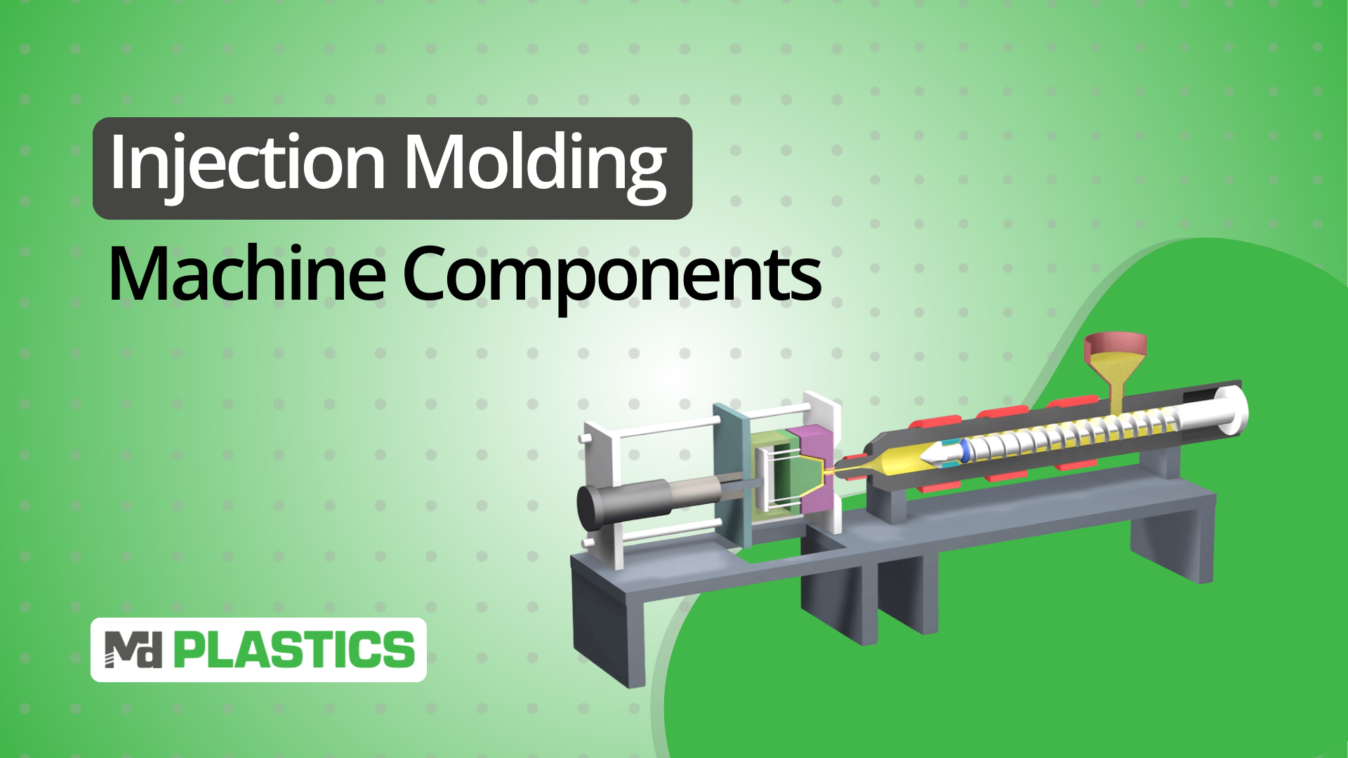
Key Components of Injection Molding Machines
Each injection molding machine component handles a specific phase of the cycle. When one underperforms, it shows up in your parts or your production metrics. Here's a concise breakdown of what each system does:
1. Injection Unit
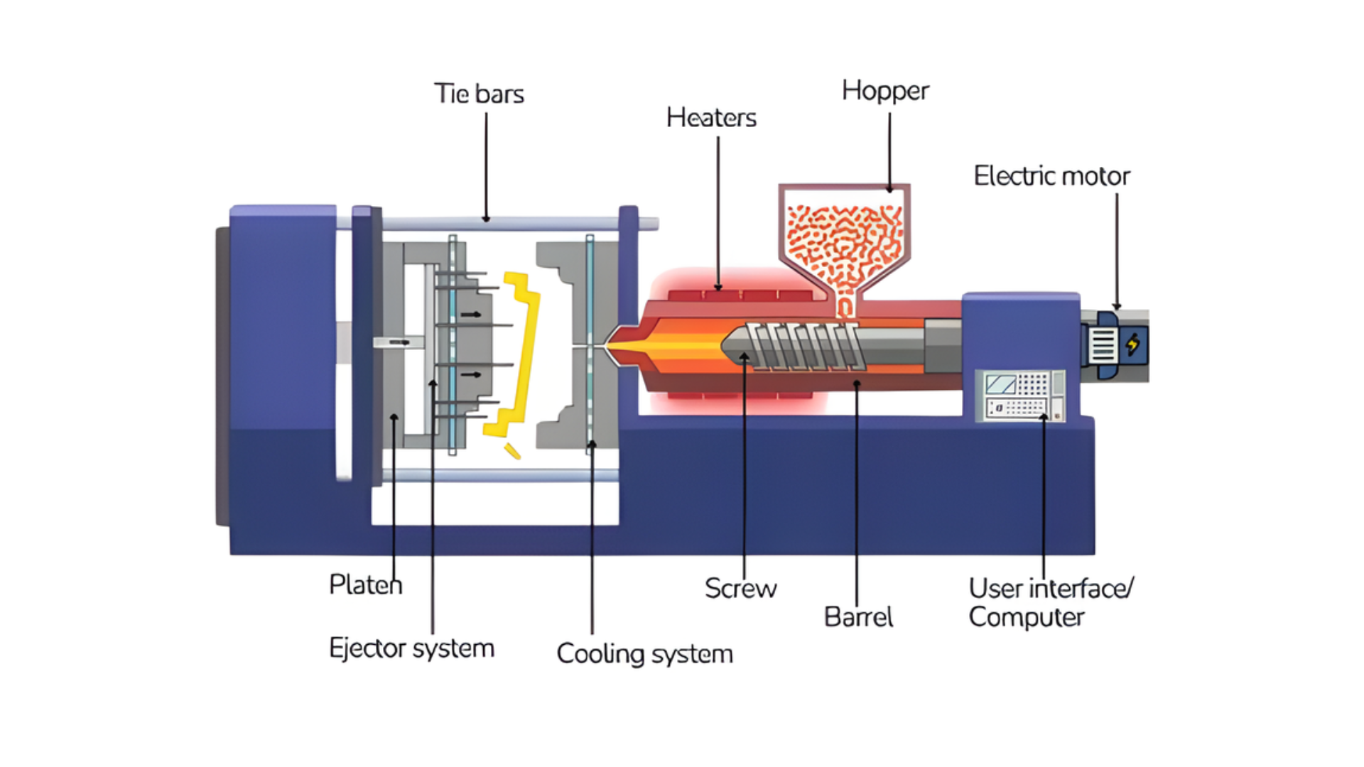
The injection unit is the heart of the injection molding process. It is responsible for melting the plastic resin and injecting it into the mold. This unit consists of several subcomponents:
Hopper: This is where plastic pellets are fed into the machine. The material is usually a thermoplastic resin that is melted before being injected into the mold.
Screw and Barrel: The screw rotates and moves the plastic through the barrel, where it is heated to the right temperature. The screw’s rotation also ensures that the material is evenly mixed before injection. The barrel houses the screw and provides the necessary heating to melt the plastic.
Injection Ram: In some machines, instead of a screw, an injection ram is used to push the melted material into the mold.
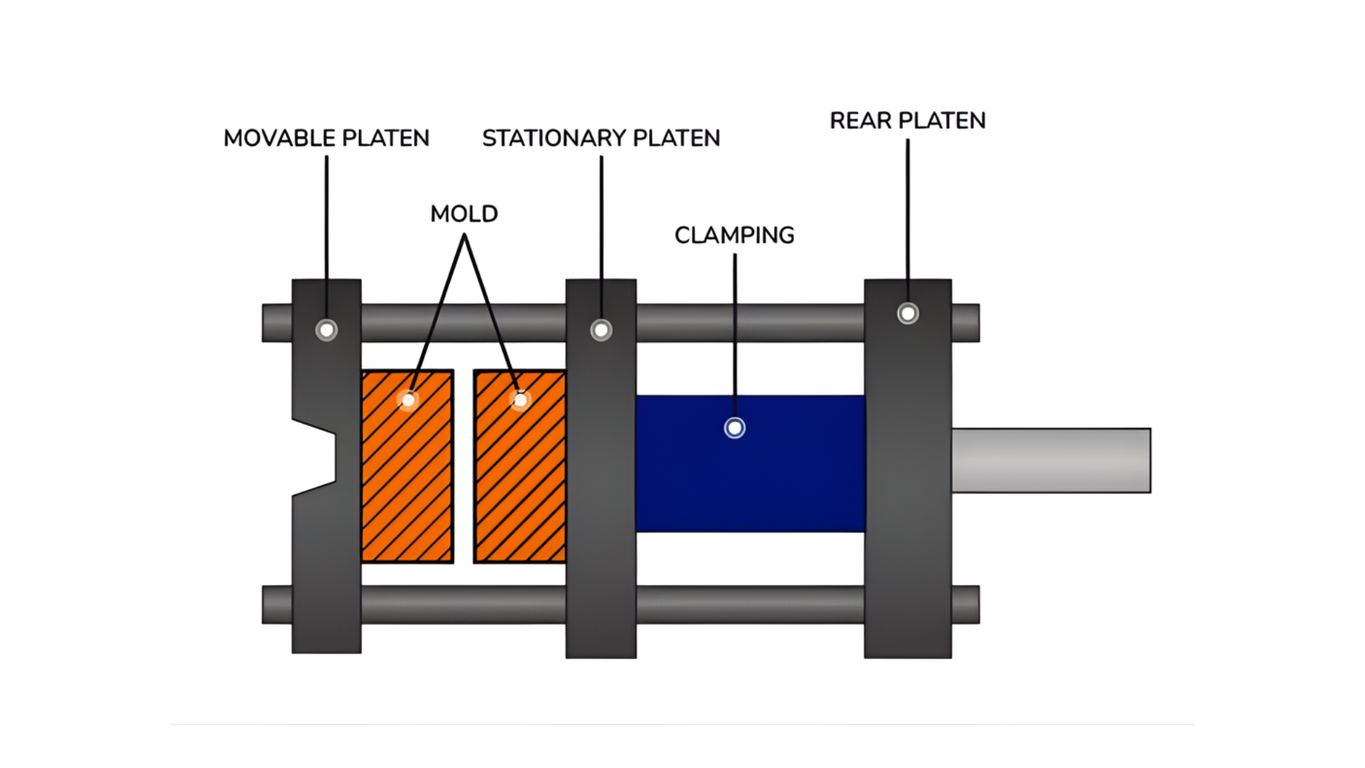
2. Clamping Unit
The clamping unit holds the mold in place and applies pressure during the injection phase. It ensures the mold stays securely closed while the material is injected. This unit consists of:
Clamps: These are the mechanical devices that apply the necessary force to close the mold. The force applied is critical to prevent the mold from opening under pressure during the injection phase.
Tie Bars: These are large, rigid bars that help maintain the alignment of the mold. They are responsible for keeping the mold halves in position during the injection process.
Mold Base: The mold base is the platform where the mold is mounted. It provides the structural support necessary to hold the mold and withstand the forces generated during the injection process.
3. Mold
The mold is a crucial component where the plastic material is shaped into the desired part. Molds are made of two halves:
Core and Cavity: The core forms the interior of the molded part, while the cavity shapes the outer surface. The mold can have various intricate features, such as cooling channels and vents, to ensure uniform molding.
Ejector System: Once the plastic has cooled and solidified in the mold, the ejector system is responsible for removing the finished part from the mold. The system uses pins or plates to push the part out without causing damage.
4. Control System
The control system is the brain of the injection molding machine. It manages all aspects of the machine’s operation, including injection timing, temperature control, pressure, and mold opening/closing cycles.
The system allows operators to set parameters for different parts, ensuring consistent quality. Modern machines are equipped with digital controllers that can be programmed to optimize the process based on real-time feedback from sensors.
5. Hydraulic System
Many injection molding machines use hydraulic systems to power the clamping and injection units. The hydraulic system is responsible for supplying the force necessary to close the mold and inject the material into the mold cavity.
The hydraulic circuit typically consists of pumps, valves, and cylinders that control the flow and pressure of hydraulic fluid.
6. Cooling System
Cooling is an essential part of the injection molding process. After the molten plastic is injected into the mold, it needs to cool and solidify to take shape.
Cooling channels within the mold allow coolant (usually water) to circulate, reducing the cycle time and ensuring that the part retains its shape once ejected.
The cooling system helps prevent defects like warping or incomplete filling.
7. Ejector System
Once the plastic has cooled and hardened inside the mold, the ejector system ensures that the molded part is removed.
The ejector system can be mechanical or hydraulic and uses ejector pins or plates to push the molded part out of the mold cavity. This is a critical step to ensure that parts are removed cleanly and without damage.
8. Feed System
The feed system consists of the hopper and the screw that deliver raw plastic pellets into the barrel of the injection unit. The hopper feeds the resin into the barrel, where it is heated and melted.
The feed system needs to operate smoothly to ensure the right amount of material is consistently supplied for the injection cycle.
9. Drive System
The drive system powers the movement of the machine components, particularly the screw and the clamp. This system can be electric, hydraulic, or a hybrid.
Electric drive systems are becoming more common due to their energy efficiency and precision control. The drive system is crucial for maintaining smooth operations and minimizing downtime.
10. Ventilation System
A ventilation system helps to remove the gases produced during the injection process. These gases can accumulate in the mold cavity and affect part quality if not properly vented.
Proper ventilation ensures that air and gas escape the mold without causing defects in the molded part, such as burn marks or trapped air pockets.
How These Components Work Together
An injection molding cycle is a sequence of timed operations. Each component hands off to the next, and timing drives your throughput and part quality.
The Cycle Breakdown
Mold closes. The clamping unit brings the mold halves together and locks them under tonnage. Your controller confirms proper closure before allowing injection to start.
Material injects. The injection unit pushes molten plastic into the cavity at programmed speeds and pressures. The hydraulic or electric drive system provides the force needed to overcome flow resistance.
Pressure holds. As the plastic cools and shrinks, the injection unit maintains pack pressure to keep feeding material into the cavity. This prevents sink marks and voids.
Part cools. The cooling system pulls heat from the mold while the material handling system prepares the next shot. This phase runs longest in your cycle.
Mold opens and part ejects. The clamping unit releases, ejector pins push the part out, and the cycle repeats.
Proper synchronization of these components is critical to prevent defects like misalignment or warping, ensuring that each molded part meets the desired specifications.
Why Plasticating Components Matter More Than Operators Realize
Most machine problems that appear in the clamp, cooling, or mold actually begin upstream in the injection unit.
Worn screws, degraded barrels, leaking non-return valves, or poor melt homogeneity create:
inconsistent cushion
unstable pressures
poor pack density
longer recovery times
cosmetic defects
dimensional drift
No amount of injection tuning or clamp-force adjustment can compensate for an unstable melt. This is why the plasticating system—the screw, barrel, non-return valve, nozzle, and melt monitoring—determines 70% of your final part quality.
At MD Plastics, we focus on the components that directly impact melt quality and consistency. Our Inject-Ex Plasticating Systems, Posi-Melt screws, plasticating barrels, and MDP non-return valves are engineered to improve shot-to-shot repeatability and reduce process variation.
Whether you're troubleshooting inconsistent fills or looking to cut cycle times, the right plasticating components make the difference. Explore our full range of injection molding solutions to see how we can help optimize your operation.
Key Considerations for Optimizing Machine Performance
Your machine's performance depends on consistent maintenance and process monitoring. Small issues compound quickly when left unchecked.
Temperature Control
Monitor barrel zone temperatures throughout your shift. Fluctuations of even a few degrees affect melt viscosity and part consistency.
Watch for:
Degraded heater bands that create hot spots
Thermocouple drift that gives false readings
Cooling water temperature variation during seasonal changes
Check your mold temperature controllers weekly. Uneven cooling creates warpage and dimensional issues that show up in your quality reports.
Cycle Time Optimization
Look at your cooling phase first. It typically accounts for the majority of your total cycle time.
Quick wins:
Verify cooling channels aren't restricted or scaled
Confirm water flow rates match your mold design specs
Test if you're overcooling and adding unnecessary time
Review injection and hold times next. Longer doesn't always mean better. You want just enough to fill the cavity and compensate for shrinkage.
Preventive Maintenance
Set a schedule and stick to it. Reactive maintenance costs more and kills your uptime.
Critical checks:
Hydraulic oil levels and contamination
Screw and barrel wear patterns
Check ring and non-return valve condition
Tie bar lubrication and alignment
Replace worn-out components before they fail. A worn barrel or check valve creates shot size variation you'll spend hours chasing through process adjustments.
Automation and Monitoring
Modern controllers can flag process drift before it becomes scrap. Use the data you're already collecting.
Set alerts for:
Injection pressure deviations outside your window
Cushion position changes that signal material inconsistency
Cycle time creep that indicates a developing problem
Automation reduces operator error, but only if your baseline process is stable. Get your fundamentals right first, then let the technology maintain them.
Conclusion
Your injection molding machine is only as good as your ability to diagnose and maintain it. When you know what each component does and how they work together, you spend less time chasing problems and more time running parts.
The complexity becomes manageable when you focus on the fundamentals: proper heating, consistent injection, efficient cooling, and synchronized control.
At MD Plastics, we've engineered plasticating solutions for injection molders since 1999. Our technology addresses the core issues that impact your operation:
How we help:
Our patented Posi-Melt™ screws deliver consistent melt homogeneity and reduce color change times
We offer MDP™ non-return valves that eliminate drool and maintain shot size accuracy
Our Inject-Ex™ plasticating systems are designed for faster recovery and tighter process windows
Our Melt-IQ™ monitoring system gives you real-time visibility into melt temperature variations
Get in touch today to discuss how our plasticating technology can optimize your injection molding operation.
Frequently Asked Questions
What are the main components of an injection molding machine?
The main components include the injection unit (hopper, screw, barrel), clamping unit (clamps, tie bars), mold (core and cavity), control system, hydraulic or electric drive system, cooling system, and ejector system. Each handles a specific phase of the molding cycle.
How does the injection unit work?
The injection unit melts plastic pellets in a heated barrel using a rotating screw. The screw then acts as a ram to push molten plastic into the mold cavity at controlled speeds and pressures, ensuring consistent shot sizes and part quality.
What's the difference between hydraulic and electric drive systems?
Hydraulic systems provide better force for high-tonnage applications and thick-walled parts. Electric systems offer superior repeatability, lower energy consumption, and cleaner operation, making them ideal for precision parts and medical or food-grade molding.
Why is the cooling system critical in injection molding?
The cooling system solidifies the molded part and directly controls cycle time. Efficient cooling prevents warpage, sink marks, and dimensional variations while maximizing throughput. Poor cooling creates quality issues and extends production time unnecessarily.
How often should injection molding machine components be maintained?
Follow a preventive maintenance schedule based on your production volume. Check hydraulic oil, screw and barrel wear, non-return valves, and tie bar alignment regularly. Replace wear components before failure to avoid shot size variation and unplanned downtime.