In injection molding, few settings influence melt quality as directly or as deceptively as barrel temperature control. Barrel temperature settings determine how consistently the screw develops melt, but they are only one piece of the melt-preparation equation.
Processors know the symptoms when the barrel profile is wrong: unmelt showing up in the part, splay from trapped moisture, drool and stringing at the nozzle, burn marks from overheated zones, viscosity swings, and intermittent short shots that seem to appear without warning.
The complication is that the barrel temperature ≠ melt temperature.
Even when every zone reads perfectly on the controller, the actual melt temperature is governed far more by shear, screw design, backpressure, and residence time than by heater bands.
That gap between displayed temperature and true melt behavior is where most processing issues originate.
This guide cuts through the guesswork.
It breaks down each barrel zone’s function, how temperature profiles influence melt development, the real physics behind melting, how to diagnose temperature-related defects, and what “good” barrel control looks like in day-to-day production.
If you need a practical, engineering-level reference for improving thermal stability and melt consistency, this is it.
Key Takeaways
Barrel temperature settings influence melting, but the actual melt temperature is driven mainly by shear, screw design, backpressure, and residence time.
Each barrel zone has a distinct function: feed (conveyance), compression (melting), metering (homogenization), and nozzle (flow control)—and incorrect zone temps cause unmelt, splay, burn, drool, and short shots.
Temperature profiles (ramp, flat, reverse) must match resin behavior; wrong profiles create viscosity swings and inconsistent part quality.
Most “temperature-related defects” trace back to poor melting, worn screws/NRVs, low backpressure, or shear imbalance, not heater settings.
MD Plastics improves melt stability upstream, making barrel temperature control easier and more predictable through advanced screws, NRVs, and real melt-monitoring tools.
Injection Molding Barrel Zones Explained
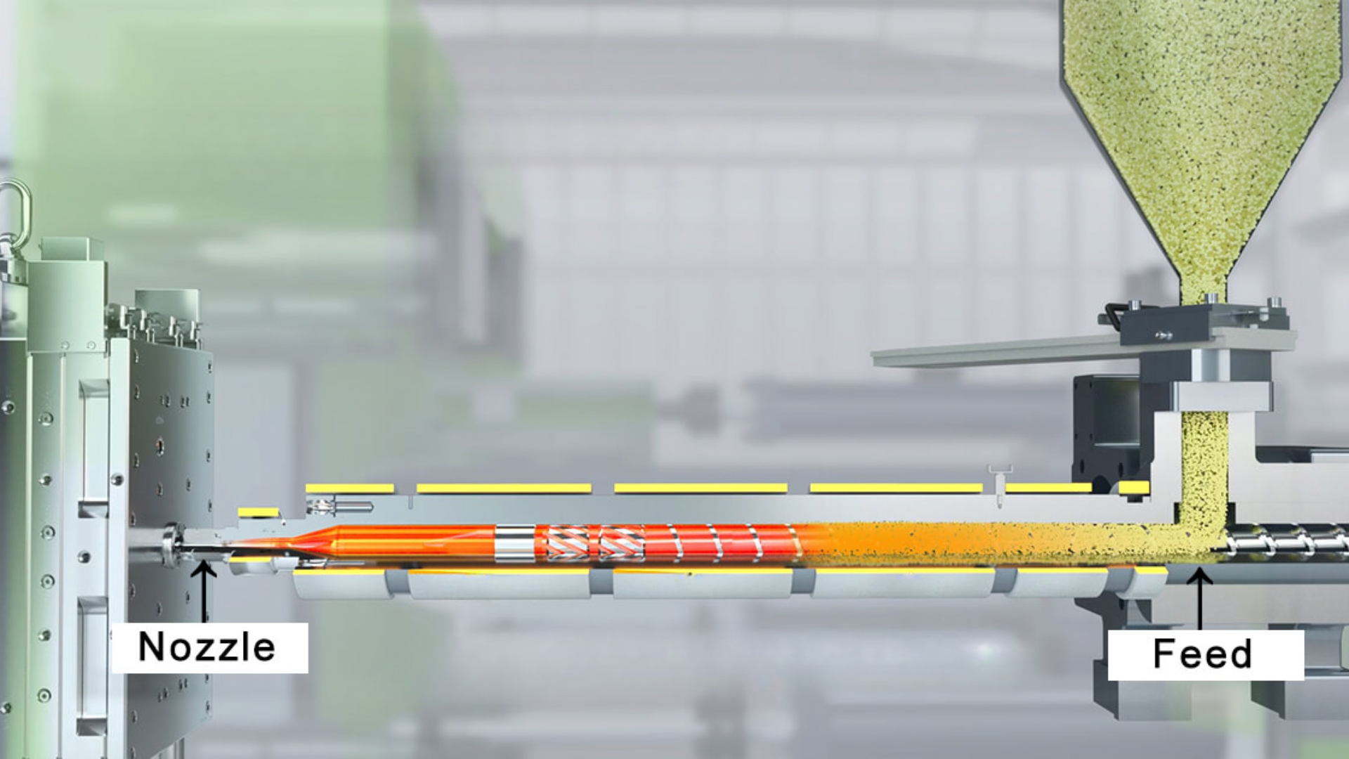
An injection molding barrel isn’t just a heated tube; it’s a staged thermal and mechanical environment divided into zones, each designed to perform a specific step in the transition from pellets → softened pellets → melt → homogeneous melt.
The temperature “profile” across these zones, not any individual setting, determines how smoothly the screw develops a stable, repeatable melt.
Below is the engineering breakdown of each zone and how its temperature influences real melt behavior.
(Zone 1) Feed Zone: Solid Conveyance + Initial Softening
Location: Directly beneath the hopper; the beginning of the barrel.
Typical Temperature Strategy: Lower than downstream zones; sometimes intentionally “cold” depending on resin (e.g., PP, HDPE) to prevent premature melting.
Role:
Prevent bridging and pellet sticking at the hopper throat.
Ensure consistent, solid conveying into the compression section.
Begin slight outer-layer softening to aid mechanical conveying without melting the pellet core.
Impact on Melt Quality:
Too hot:
Pellets stick to the barrel → screw starvation
Surging and inconsistent melt density
Early melt → poor compression and unstable viscosity
Too cold:
Un-melt carries into the compression zone
Screw torque spikes
Pellet grinding → dust → discoloration or contamination
Defects Caused by Wrong Feed-Zone Settings:
Splay from trapped moisture
Silver streaking
Melt/color uniformity issues
Surging due to stick–slip conveying
(Zone 2) Compression Zone: Primary Melting & Energy Input
Location: Middle section of the barrel, where the screw’s channel depth begins to reduce.
Typical Temperature Strategy: Warmer than Zone 1 to begin melting aggressively, but not so hot that pellets melt prematurely or create an early melt pool.
Role:
This is where most melting actually occurs.
Pellets collapse and transition into a molten pool.
Screw geometry (compression ratio, channel depth reduction) applies shear, generating the bulk of thermal energy.
Impact on Melt Quality:
Zone 2 temperature complements shear; it cannot replace it.
If too cold:
Unmelted particles remain in the melt pool
Flow lines and black specs
Higher injection pressure required
If too hot:
Early melt causes screw inefficiency
Shear overheating → yellowing, burn marks
Resin degradation in long residence-time runs
Troubleshooting Indicators
Unmelt specks → Zone 2 too cold or insufficient backpressure
Degradation/yellowing → Zone 2 too hot or long residence time
Rising torque → feed zone too cold or resin moisture
(Zone 3) Metering Zone: Homogenization + Viscosity Stabilization
Location: Downstream end of the barrel, just before the front zone/nozzle.
Typical Temperature Strategy: Slightly hotter or equal to Zone 2, depending on resin; target is a stable, fully molten, homogeneous melt.
Role:
The final stage of melting refines the melt to an even, predictable consistency.
Homogenizes pigments, additives, and recycled content.
Establishes melt viscosity entering the front zone and nozzle.
Impact on Melt Quality:
Direct influence on shot-to-shot repeatability.
Too hot:
Drool/stringing at the nozzle
Overly fluid melt → over-packing → flash
Too cold:
Viscosity spikes
Pressure-limited shots
Fill the imbalance in multi-cavity molds
Defects from Incorrect Metering-Zone Settings:
Short shots
Hesitation marks
Cavity-to-cavity dimensional drift
(Zone 4) Nozzle Zone: Flow, Drool Prevention, Gate Freeze Behavior
Location: At the barrel exit, directly before the sprue bushing or hot runner.
Typical Temperature Strategy: Often equal to or slightly hotter than Zone 3 for shear-sensitive resins; sometimes slightly cooler for drool control.
Role:
Maintain melt temperature consistency right before injection.
Prevent premature cooling at the tip.
Provide a stable flow into the gate without degradation or freeze-off.
Impact on Melt Quality:
Too hot:
Drool/stringing
Gate smear
Stringing as the mold opens
Higher risk of burn on shear-sensitive materials
Too cold:
Cold slugs
Flow lines and hesitation
Early gate freeze-off → short shots
Special Processing Notes
PC/PMMA: nozzle is often the hottest zone
TPE/PE: nozzle sometimes runs cooler to prevent drool
Hot runners: nozzle zone becomes more critical for gate freeze timing
Understanding each barrel zone’s role allows processors to diagnose melt inconsistencies faster and set temperatures based on polymer behavior, not outdated machine charts or guesswork.
Barrel Temperature vs Actual Melt Temperature
One of the most common misconceptions in injection molding is assuming that the numbers on the barrel’s heater bands equal the melt temperature inside the screw channel.
They don’t; not even close.
Barrel temperature influences melt, but the melt temperature you measure at the nozzle or with a probe is determined primarily by mechanical energy, not heater setpoints.
What Actually Controls Melt Temperature
The melt temperature is shaped far more by shear and material behavior than by heater bands:
Screw shear: the main source of heat generation
Backpressure: increases shear + mixing → raises melt temperature
Screw design: compression ratio, flight depth, mixing elements
Residence time: longer residence time raises the melt temperature and risk of degradation
Moisture and additives: influence viscosity and shear sensitivity
This is why two machines with identical barrel profiles can produce melts that differ by 20–40°F.
Why Barrel Zones Can Be “Perfect” but Melt Temperature Is Still Wrong
Because heater bands only affect the barrel wall, not the melt itself.
Common scenarios:
Melt reads too hot, even with moderate heater settings → shear is excessive
Melt reads too cold despite high heater settings → insufficient shear, worn screw, worn NRV
Melt uniformity looks poor → backpressure too low or screw design mismatched to resin
Melt appears stable during idle, but drifts during production → shear heating changes under load
Heater displays tell you what the steel is doing.
They do not tell you what the polymer is experiencing.
Why Relying on Heater Setpoints Gives False Confidence
Heater-band temperatures:
Don’t account for shear variation during the plasticizing cycle
Don’t reflect screw/barrel wear
Don’t show melt-temperature gradients across the melt pool
Don’t reveal viscosity swings that cause pressure instabilities
This is why some processors “chase the heaters” when defects appear, even though the root cause is mechanical, not thermal.
Why Real Processors Measure Melt with a Probe
A melt probe (or MD Plastics Temp-Sense™) gives the only meaningful temperature reading:
It measures polymer temperature directly at the nozzle or the end of the barrel
It captures shear-induced heating that heater bands cannot measure
It reveals melt inconsistency long before quality drifts in the mold
If you’re adjusting heater zones without probing the melt, you’re tuning blind.
The contrast below shows why processors who rely only on heater-band readings often misdiagnose melt-temperature problems.
What Processors THINK Controls Melt | What ACTUALLY Controls Melt |
|---|---|
Barrel heater setpoints | Screw shear + compression ratio |
Zone temperatures | Backpressure |
Nozzle temp alone | Residence time |
“Band cycling stability” | Material moisture & additives |
Heater uniformity across zones | Screw/barrel wear |
Even when processors understand that shear, not the heater bands, controls melt, another trap still causes major instability: assuming heater bands deliver steady, accurate heat.
They don’t.
In real production, heater bands cycle, drift, override, and lag, which introduces thermal noise into the melt long before shear ever compensates for it.
That brings us to one of the most overlooked causes of inconsistent melt temperature:
Heater Band Cycling, Overrides & Thermal Lag
Heater bands do not provide continuous heat. They pulse, overshoot, lose contact, and sometimes fight your setpoints. If you rely on their displayed temperature alone, you’ll misdiagnose melt problems almost every time.
Heater Band Cycling, Why ON/OFF Behavior Creates Melt Instability
Heater bands maintain temperature by switching ON to add heat, then OFF as the barrel cools. This constant cycling creates a barrel-wall temperature ripple that the melt “feels” as inconsistency.
Why bands cycle:
PID control pulsing to maintain temperature
Poor band-to-barrel contact
Heat loss differences across zones
Why it matters:
Fast cycling = unstable melt temperature
Long ON-time = weak or failing heater band
Uneven cycling zone-to-zone = uneven thermal conditions for melting
A band can show perfect numbers while the melt is drifting 20–40°F.
Temperature Overrides: When the Machine Ignores Your Setpoint
Older machines or stressed heater circuits sometimes override the operator’s programmed temperature.
Overrides occur when:
A band cannot hit the setpoint
A thermocouple senses abnormal drift
The controller throttles output to prevent overheating
Adjacent zones compensate for a weak band
Why it matters:
Overrides disguise real hardware issues
Melt temperature becomes unpredictable
Processors often “chase the heaters” instead of finding the failed zone
Thermal Lag, Why the Display Reads 450°F, but the Melt Is 390°F
Thermal lag is the difference between the heater-band temperature and the actual melt temperature.
Causes:
Air gaps between band and barrel
Oxidation/resin buildup insulating the barrel
Worn screws generate less shear
Poor insulation is forcing bands to overwork
Thermocouples reading the barrel wall—not the melt
Result: Perfect barrel temps + unstable melt = classic thermal lag problem.
Quick Heater Band Inspection Checklist
A fast maintenance audit that prevents 80% of heater-related melt swings:
Check contact: Bands must sit flush with no air gaps.
Check cleanliness: Remove oxidation, rust, or resin char between band and barrel.
Check thermocouples: Ensure tight seating; loose sensors read ambient air.
Check amperage: Uneven draw indicates a failing band or bad SSR.
Simple inspections prevent months of unnecessary “temperature adjusting.”
Understanding how heater bands behave in the real world makes one thing clear:
The temperature profile you set is not necessarily the profile your melt experiences.
Now that we’ve covered how hardware influences heat delivery, the next step is choosing the correct barrel temperature profile for your resin and melt behavior.
Correct Barrel Temperature Profiles
Barrel temperatures aren’t just numbers; they’re a thermal strategy. The profile you choose determines how pellets soften, how melt develops, and how consistently viscosity stays from shot to shot.
Below are the three primary profiles processors use and when each one makes sense.
Standard Ramp Profile
Most common; increases temperature from Feed → Compression → Metering → Nozzle
Best for: PP, PS, ABS, many general-purpose resins.
Why it works: A gradual temperature increase matches the screw’s melting mechanics—pellets soften slowly in Zone 1, collapse in Zone 2, and refine in Zone 3.
Benefits:
Predictable melt progression
Good control over viscosity for mid-range shear materials
Prevents premature melting in the feed zone
Risks:
If the ramp is too aggressive, the front zone overheats → degradation, yellowing, burn marks
Excess front-zone heat can also increase drool/stringing
Flat Profile
All barrel zones run at or near the same temperature
Best for: Shear-sensitive resins such as PC, PMMA, and some TPUs.
Why it works: These polymers develop most of their melt energy from shear, not temperature, so the barrel simply needs to maintain a stable, uniform environment.
Benefits:
Excellent melt uniformity
Reduces the risk of thermal degradation at the front
Helps maintain color stability in sensitive materials
Risks:
Requires consistent screw shear; if the screw design is weak or the backpressure is low, you can get unmelt or poor mixing
Flat profiles amplify any upstream issues in melting
Reverse Profile
Zone 1 hottest → temperatures gradually drop toward Zone 3
Best for: High-viscosity resins, tacky pellets, and moisture-sensitive nylons (PA6/PA66) are used when feed-zone slippage is a problem.
Why it works: A hotter Zone 1 improves solid conveying and prevents pellets from slipping or “stalling.” Downstream zones run cooler to control final viscosity.
Benefits:
Stabilizes feed for slippery or low-friction pellets
Reduces screw surging in high-viscosity resins
Helps dry sensitive nylons by increasing early thermal input
Risks:
Easy to overheat Zone 1 → bridging, sticking, screw starvation
If downstream temps are too low → unmelt, pressure spikes
Rarely used unless the material demands it
Recommended Profile by Resin (Quick Reference)
Resin | Best Temperature Profile | Reasoning |
|---|---|---|
PP | Standard Ramp | Predictable melting, stable viscosity, prevents feed-zone tack. |
PS | Standard Ramp | Low shear sensitivity; benefits from progressive heating. |
ABS | Standard Ramp (mild) | Avoids front-zone overheating that causes yellowing. |
HDPE / LDPE | Standard Ramp | Prevents premature melt in feed zone; controls drool. |
PC | Flat | Highly shear-sensitive; uniform thermal environment required. |
PMMA | Flat | Reduces risk of burn or discoloration. |
Nylon (PA6/PA66) | Reverse or Mild Ramp | Helps with feed slippage; requires moisture-sensitive control. |
POM | Standard Ramp | Stable crystalline melt development; avoid overheating. |
TPU | Flat | Sensitive to thermal degradation; uniform heating preferred. |
GF Nylons | Mild Ramp or Reverse | Higher viscosity + abrasive; needs stronger early conveying. |
The fastest way to validate (or correct) a temperature strategy is to troubleshoot the defects it creates: unmelt, splay, drool, burn, short shots, and viscosity shifts.
The diagnostic chart below connects each defect directly to its most likely barrel-temperature cause.
Injection Molding Temperature-Related Defects: Causes & Fixes
Defect | Likely Temperature-Related Cause | Corrective Action (explicit) |
|---|---|---|
Splay/silver streaks | Feed zone too cold; wet resin; low shear → low actual melt temp | Raise Zone 1 slightly, dry resin/verify dryer, increase screw RPM to add shear, reduce decompression if pulling air |
Unmelt particles/specs | Zone 2 too cold; low backpressure; worn screw → poor melting | Raise Zone 2, increase backpressure 25–50 psi, increase screw RPM, inspect screw/barrel for wear |
Burn marks / black streaks | Zone 3 or nozzle too hot; long residence time; over-shear | Lower Zone 3 & nozzle temps, shorten recovery time, reduce screw RPM/backpressure if overheating |
Short shots (temperature-driven) | Front zone/nozzle too cold; high viscosity; cold slug at nozzle | Raise Zone 3 & nozzle temps, increase backpressure, purge cold slug, reduce decompression |
Drool / stringing at the nozzle | Nozzle too hot; metering zone too hot; excessive decompression | Lower nozzle 5–10 °C, trim Zone 3, reduce decompression, add suck-back delay |
Color swirl / poor mixing | Metering zone too cold; low shear; low backpressure | Raise Zone 3, increase RPM, increase backpressure, verify masterbatch let-down |
Jetting / flow lines | Front too cold → high viscosity jet; nozzle too cold; injection too fast with cold melt | Raise nozzle/Zone 3, warm gate area, slightly reduce V→P transfer speed, ensure proper melt temp |
Hesitation marks / flow hesitation | Temperature gradient across zones; front cooler than mid; variable viscosity | Flatten Zone 2→3 profile, raise Zone 3, stabilize screw recovery (RPM/backpressure) |
Gate blush/smear | Nozzle too hot; melt too hot at entry | Lower nozzle, lower Zone 3 a few degrees, optimize decompression/start-of-injection timing |
Cold slug / freeze-off at the gate | Nozzle too cold; long sprue exposure; front band cycling | Increase nozzle temp, insulate sprue/nozzle, verify band function & contact |
Voids/bubbles (thermal origin) | Melt too cold when packing; gas stays; moisture | Raise Zone 3, increase pack pressure/time, dry resin, reduce injection speed if entraining air |
Sink (temperature-related) | Melt too cold → poor packing; front zone cools early | Raise Zone 3, raise mold temp if allowed, extend/raise pack, ensure consistent melt density (backpressure) |
Warp (thermal) | Non-uniform melt temp; inconsistent recovery heat; hot spots in front | Stabilize Zone 2–3, reduce RPM if overheating, tighten melt temp window (measure actual melt) |
Gloss/haze variation | Inconsistent melt temp shot-to-shot; nozzle temp swings | Tighten Zone 3 & nozzle control, replace cycling bands/relays, insulate nozzle, stabilize recovery |
Dimensional drift (over time) | Melt temp creeping up/down; heater band cycling; residence-time changes | Audit heater band cycling, verify melt with probe, lock recovery time, trim Zone 3/nozzle 2–5 °C |
Cavity imbalance (multi-cavity) | Melt temp non-uniform → viscosity split; front zone instability | Tighten Zone 3 control, stabilize backpressure/RPM, verify hot-runner temps if used, measure actual melt |
Cycle-time creep (thermal) | Response lag/overrides; poor insulation; bands cycling hard | Replace/seat bands, add barrel insulation, check power zones/SSR, reduce setpoints if overshooting |
Quick reality check
Barrel setpoints ≠ melt temperature. If fixes don’t stick, measure actual melt at the nozzle (pyrometer/needle probe) and adjust Zone 2–3, RPM, and backpressure to hit the true melt window for the resin.
90% of “temperature defects” resolve by dialing Zone 2 (melting), Zone 3 (metering), backpressure, and screw RPM, not just the nozzle.
How MD Plastics Improves Barrel Temperature Control
Barrel temperature control works only when the melt entering each zone is already stable. Most “temperature problems” actually originate in the plasticating system, screw shear, NRV sealing, and melt homogeneity, not in the heater bands.
MD Plastics strengthens the part of the machine that creates melt quality, making temperature control far more predictable.
1. Why Melt Quality Begins Upstream
Barrel zones regulate heat, but they cannot fix poor melting.
Shear, compression ratio, and mixing elements generate most of the melt energy.
When these are inconsistent, processors end up chasing temperatures that can never stabilize.
Stable melt → stable viscosity → easier barrel temperature control.
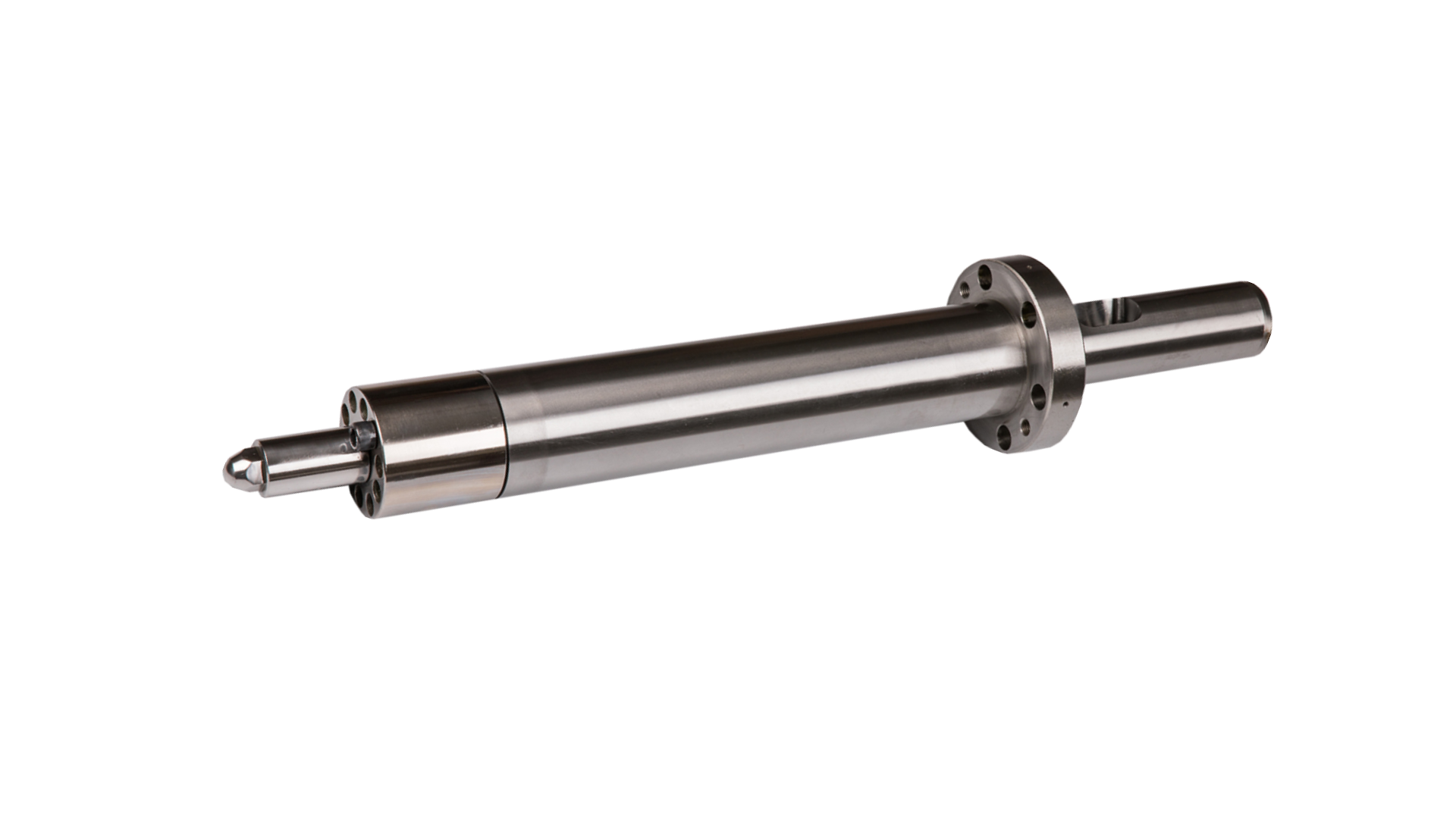
2. Components That Improve Melt Consistency
Custom Screws: Generate uniform shear and melting, reducing unmelt and viscosity swings.
Precision Barrels: Improve thermal stability and reduce heater cycling.
MDP™ Non-Return Valves: Eliminate backflow, critical for consistent melt density and shot volume.
Optimized Nozzle Tips: Reduce drool, freeze-off, and cold-slug defects without overheating the front zone.
Result: Better melt quality with less dependence on extreme temperature profiles.
3. Real Melt Monitoring (Melt-Profiler™, Melt-IQ®, Temp-Sense™)
Heater readings show steel temperature, not polymer temperature.
MD Plastics’ monitoring tools measure:
Actual melt temperature
Shear-induced heat
Viscosity stability
Early wear indicators
This lets processors set barrel temperatures based on real melt behavior instead of guesswork.
4. Retrofit Benefits
Upgrading only the plasticating end can immediately improve:
Melt-temperature stability
Start-up repeatability
Shot consistency
Sensitivity to heater-band cycling
Most plants achieve major gains without buying a new machine.
Conclusion
Barrel temperature settings matter, but melt physics matter more. Heater bands influence the barrel wall, while shear, screw geometry, backpressure, and residence time determine the melt temperature the polymer actually experiences.
When melt quality is stable, barrel zones stay stable, defects decline, and process windows tighten naturally.
Consistent melt is the foundation of injection-molding repeatability.
Stabilize the melt, and barrel control becomes easy. MD Plastics combines on-site process analysis with engineered plasticating hardware and real melt monitoring to remove upstream variability and maximize productivity.
Ready to align barrel control with true melt behavior? Book a data-driven melt evaluation.
FAQs
1. What is the purpose of each barrel zone in injection molding?
Each zone performs a different thermal function:
Zone 1 (Feed): solid conveying + controlled softening
Zone 2 (Compression): primary melting and shear generation
Zone 3 (Metering): homogenization and viscosity stabilization
Zone 4 (Nozzle): flow control, drool prevention, and gate freeze management
Together, they manage pellet transition from solid → melt → consistent melt.
2. Why doesn’t the barrel temperature match the actual melt temperature?
Because heater bands heat steel, not polymer. Actual melt temperature is shaped mainly by:
shear energy
screw design
backpressure
residence time
It’s common for melt temperature to be 20–40°F different from barrel readings.
3. What temperature profile should I use for PP/ABS/PC/etc?
General guidance:
PP, PS, ABS → Standard Ramp
PC, PMMA → Flat
Nylons, tacky pellets → Reverse or Mild Ramp
Profiles should always be validated with actual melt-temperature measurement, not just heater displays.
4. How do I know if my barrel zones are too hot or too cold?
Typical indicators:
Too cold: unmelt, high injection pressure, hesitation, short shots
Too hot: drool, stringing, burn marks, discoloration
Confirm with a melt probe—zone temperatures alone can be misleading.
5. Why do heater bands cycle so frequently?
Bands cycle ON/OFF to maintain the setpoint using PID control. Heavy cycling usually means:
poor band-to-barrel contact
insulation loss
failing heater band
temperature override mode in older machines
Cycling creates thermal noise that destabilizes melt temperature.